Back to Diane's HomePage
Diane's Fusor Page
 Deutsche Version
by
Diane Neisius
updated: March 5, 2011
Content
Intro - "Laser Diane" Builds a Fusor?
I have to admit I'm a bit lazy.
I also have to admit I once said about the argon ion laser, with its bore plasma temperature of 30,000 degrees it would be the the limit of what an amateur can build. "Next stop, nuclear fusion reactor", I joked. If only had known...
After 15 years of laser making and a number of working lasers the next laser wasn't a real challenge any more. Ok, there are a few I would like to build yet, but some different project wouldn't have been that bad. Of course if it means I hadn't to set up entirely new all my lab stuff. And then I found a copy of the well-known paper of R. Hull about the homebuilt Farnsworth-Hirsch fusor.
An amateur fusion reactor? - ("Uhm... well, Dear...")
That's what I thought at the first moment. But continued to read. Had some deep thoughts. Did some recherche. Realized it would work indeed. Some really rewarding next project.
Well, but...
The home-built fusor instructions available at the web made me not completely happy.
- I didn't want to exchange my beloved old one-staged vacuum pump (paid from my first true salary) against a new two-staged one.
- My home-brewed high voltage supply I also didn't want to set up new.
- To be honest, the production of neutrons isn't only total uninteresting for me, I'm also convinced it's unnecessary dangerous for the amateur. Despite of that, I have no single detector for it. And finally there is no room for a nuclear trash can in my basement.
- After all, there is this alibi term of "demo fusor" I'm not comfortable with. A fusor which does no fusion is not a fusor but an ion multipactor or a spherical focus diode. Maybe you smile about the pedantic mathematican, dear reader. Just think about that: a laser which doesn't produce a laser beam isn't called a "demo laser". But LED, neon sign tube or scrap.
So, my fusor, should it become one, would have to earn its name.
But despite of all that, a fusor is a quite nice thing. A small artifical star in a retort, transmutation of elements, incredible romantic. About the stuff mentioned above, there should be another way to make it work?! Of course all people tell it will not work by another way, but didn't they all tell me in 1982 an amateur couldn't make her own laser...?
Review of old physics books and astrophysical publications brought me to the trace of helium. A helium discharge shows a lot of the interesting low-pressure stuff already at quite high pressure - for it permits charged particles the largest mean free paths possible in a gas. Not the least, purchased as balloon helium it is cheapest of all gases except maybe plain old air.
And wasn't there a nuclear reaction which forms carbon out of three helium nuclei without emitting nasty neutrons...?
And... hadn't I a lot of experience to make lasers work by applying short violent current pulses - should work for a fusor, too?
To make it short, I had a lot of new ideas - as it's always the case if some related disciplines like fusors and lasers touch. About the results, what worked and what didn't, I will publish here.
Carbon will not be one of the results, that became quite clear after some short calculations - at least not in my lifetime left (see below). There's just a chance to get a partial reaction which temporary forms beryllium-8. Only one nucleus every few minutes, and it will decay immediately back to two heliums. Just enough for a fusor to prove it deserves the name.
I'm quite sure there are different methods of plasma temperature measurement than neutrons from deuterium fusion. Even if, as it seems to be the case, it will not be possible to prove formation of beryllium-8 by means of a direct detection.
Part I: Theory and Some Prepearing Experiments
Fusor Basics
A lot of information about fusors is available in the web, e.g. Wikipedia or fusor.net so I give just the basics here.
 |
|
Diagram 1.
Schematic cross-section of a fusor. The vacuum vessel is light blue, dotted lines mark the electrode grids. Paths of electrons and positive ions are shown by green and yellow arrows. At center the small grey/violet cloud marks the position of the plasma focus (also called poissor). |
Basically, a fusor is nothing else than a neon tube in a quite unusual shape - it has two concentric spherical electrodes. Vacuum tubes of this kind, called spherical focus diodes, have been examined in the 1920ies by Katherine Blodgett and Irvine Langmuir, and already in this early time there was noticed a luminescent spot in the center of the diode but took no further attention. Such did Philo Farnsworth in the 1950ies, who saw a chance to make a working fusion reactor of this device (he also first named it a "fusor"). Farnsworth and his co-workers could demonstrate nuclear fusion in their machines but never got anywhere near a net energy generation. Funding for the research program was cut by end of the 1960ies.
It was in the 1990ies the fusor had a revival and was brought to some commercial use as a simple-to-use neutron source. Due to its simplicity, since that time it also has a "fan community" of amateur researchers.
The principle of the fusor isn't hard to understand. As mentioned, it consists just of a spherical vacuum vessel with two concentric grids in it. If a voltage of some kilovolts is brought upon it (most common is to make the inner grid negative), like in a neon tube a glow discharge starts if the gas pressure in the vessel is low enough. Electrons move towards the positive charged outer grid (green in the diagram above). At collisions with neutral gas atoms, also some positive ions are produced which immediately move towards the negative inner grid.
If pressure is quite low there are few further collisions between electrons/ions and gas atoms (one says, the mean free paths of the particles become large). It can happen now an electron or ion travels all the distance between the grids in a straight line and becomes quite fast. Approaching the grid, most will slip through a mesh and continue to travel that direction.
The electrons will crash into the wall of the vessel. The sudden braking generates heat, xrays and, in case of a glass wall, some bluish fluorescence. Because of in practice the device never is a perfect sphere and electron paths are easily disturbed (e.g. by external magnetic fields), they tend to focus to certain points on the wall, burning a hole in it if plastic. That's the reason why cheap desiccator chambers made of plastic are not suitable for a fusor vessel.
A glass wall will transmit xrays of higher energy so grid voltage should be kept in a limit or some lead shielding must be applied.
Contrary to the electrons the ions, coming from all possible directions, collect in the center of the sphere where they do high-velocity crashes into each other. A very hot spot forms which becomes visible as a shiny plasma focus. A device like this is called a spherical focus diode.
If the gas pressure is decreased still further, the mean free paths of the particles become larger and larger. An ion deflected in the center or just flying straight through it without collision will pass the inner grid again, regardless of the direction it travels. At the same moment it will be electrostatically repelled by the positive charged outer grid, softly braked until it stops and its direction reverses. The ion now accelerates again towards the center, prepeared for another collision. This kind of machine is called an ion multipactor. The trick to capture ions in the center by electrostatic repulsion is called inertial electrostatic confinement or short IEC.
If the grids are precisely aligned, the plasma focus can achieve a tremendeous ion density. If their velocity is fast enough ions may also overcome the electrostatic repulsion of two approaching nuclei so they have a chance to fuse. At this moment, if there is the chance of some single fusion reactions in the plasma focus the device is a fusor.
A technical advantage of it is the fact that ions which missed a fusion get a "new chance" by the confinement method of the multipactor. But exactly this advantage also is reason for the main design problem of the fusor: for every new try the ions must pass the inner grid. And, as coarse as its mesh may ever be, they finally hit a grid wire. The energy carried by such an ion will be lost.
Usually by the ion hits the inner grid of a running fusor is white-hot. That's a major problem for grid life-time. Some new concept of Robert Bussard plans to protect the grids by magnetic fields.
Latest research points to an additional problem. The ion collisions deflect particles by quite different velocities. Ideally the initial ion velocities were identical, but after a few collisions there is a wide velocity variation. Still most ions will have a more or less average velocity but there are also a lot much slower or much faster ions. This process is called thermalization, and obviously it happens much faster than expected.
The fast ions pose the problem in this case. It is possible they collected enough energy to withstand the repulsion of the outer grid so they can escape from confinement. Again, the energy carried is lost to the process.
Until now all these problems prevented net energy generation by the fusor device.
Glow Discharge and Cathode Ray Tube
In the time I built lasers I rarely had any business at pressures below approx. 266 Pa (old unit: 2 Torr). So it was sane to prepeare by some simple glow discharge experiments. Similar way I started laser work in the 1980ies: practical experience about vacuum aparatus can't be learnt by reading books about.
 |
|
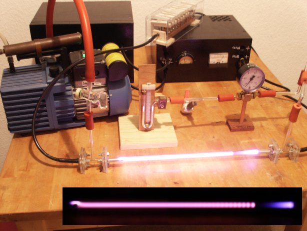
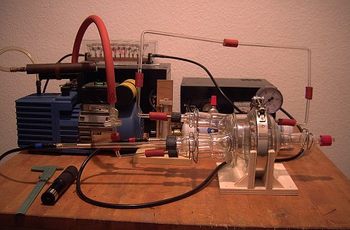
Picture 1.
Setup for simple glow discharge in air at approx. 20 Pa (old unit: 0.15 Torr or 150 Micron). Visible lab stuff is the neon sign transformer and the voltage doubler/rectifier (black boxes), some vacuum gauges and my rotary vane vacuum pump. |
At pessures below 133 Pa (1 Torr) the classical structure of a glow discharge can be watched (see inset small picture above, l.t.r.). A long positive column is pink in air, followed by the Faraday dark space which leads into the blue-violet negative glow. The latter is seperated from the cathode by the Hittorf (or, Crookes or, cathode) dark space.
Being an amateur, it's always rewarding to review the literature of the time a certain science discipline just has been discovered. That time even professional scientist were just beginners - so their papers can give valuable hints, for example about conditions for formation of electron or ion beams (also called cathode or canal rays in old papers). Concerning glow discharges, it's mentioned helium was quite often used for it shows some very specific fluorescence: e-beams excite it to green glow, ion beams to an ivory-yellow glow. The positive column shows pink glow. So the different phenomea can be identified quite easy.
Helium has some more advantages. Running glow discharges, it is noticed quickly that the zones near the cathode tend to expand if the gas pressure is lowered. In a helium discharge, the cathode zones are far more expanded than in other gases already at higher pressures - kind of "pressure bonus".
By some trick the position of the zones can even be used for pressure measurement. It has been found that in a glow discharge for a constant voltage the product of pressure and cathode dark space length is a constant:
p * d = const.
Work from the 1920ies showed up for higher voltages (>2kV) there is hardly any variation of the constant if the voltage is changed. But it sensibly depends on the type of gas in the tube. Some values are:
| Helium | 533 | Pa * mm |
| Hydrogen | 266 | Pa * mm |
| Air, Argon, ... | 133 | Pa * mm |
So we can quantify the helium pressure bonus: a 13 Pa (0.1 Torr, 100 Micron) discharge has the same appearance as an air discharge of 3.25 Pa 0.025 Torr, 25 Micron). In a fusor, that difference may show a whole new world...
As a side effect, the discharge automatically shows at which pressure it runs. It would be quite hard to estimate cathode dark space length for the spherical fusor grids, so an assistant cathode which allows easy reading of d could be added in a side arm of the vessel. Alas, a simple vacuum gauge for the pressure range 266 - 7 Pa is ready.
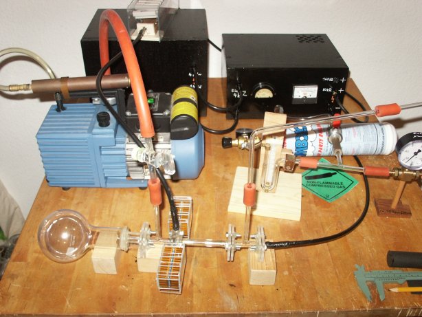
Picture 2.
Here the simple glow discharge tube was upgraded by a hollow anode and a glass bulb behind it. A small refill cylinder for party balloons serves as helium reservoir.
Note the massive heat sinks at the anode structure. |
|
 |
Using the freshly gained knowledge, I set up a primitive cathode ray tube. Despite of some minor heat problems which required cooling, it worked quite well. At a helium pressure of 40 Pa (0.3 Torr) there forms a strong e-beam which becomes visible by green gas fluorescence in the bulb and a bluish fluorescence where it hits the glass wall.
 |
|
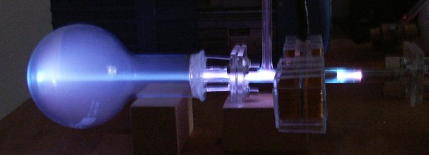
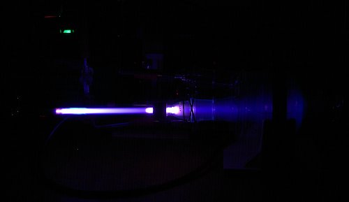
Picture 3.
Running the CRT, voltage approx. 8500 V. E-beam and fluorescent spot can be easily shifted by a magnet brought close to it. This way it also can be proven the negative glow of the discharge originally is e-beam fluorescence, too.
|
Only a guess is the yellow glow of ion beams close to the cathode end. Reverting the voltage, it can be produced by the same tube: a deep yellow ion beam then stretches up to 5 cm into the glass bulb. That's quite interesting, for in a future fusor setup ions should make the distance to the plasma focus... using the CRT, a lot of initial research concerning the fusor run conditions can be done.
Helium Fusion?
Nearly all people interested in nuclear fusion heard about the fact the sun produces all of the energy it radiates by fusion of hydrogen.
Less known is what happens if the hydrogen in sun's center runs low. Hydrogen fusion will continue in a shell around the center core. Which, in turn, now consists entirely of helium, the fusion product.
While the helium core contracts, the outer shells of the sun will expand turning our star into a red giant stadium of its life. At some time the contracting core meets conditions of density and temperature which allow ignition of the next stage of nuclear fusion: helium fuses to carbon. This triple alpha reaction takes some steps to perform:
| |
Step 1: 4He + 4He <--> 8Be |
| |
Step 2: 8Be + 4He <--> 12C(*) |
| |
Step 3: 12C(*) --> 12C + gamma |
If some amount of carbon has been produced, a side branch of the reaction starts:
| |
Step 4: 12C + 4He --> 16O + gamma |
All carbon and oxygen of the universe, even the one forming our bodies and food or the one we are breathing has been processed this way in the cores of old stars. Steps 1 and 2 of the reaction are equilibri which means they also can be done in reverse. The asterisk at the carbon symbol denotes a highly excited nuclear state of the carbon; by 99.9% probability it will decay back to beryllium and helium, just 0.1% will take step 3 to set free stable carbon and energy.
Sadly the whole nuclear reaction (which very well could run in a fusor too) has some weak point, the beryllium isotope 8Be. It is so unstable its lifetime is only 10-16 seconds until it blows up into two helium nuclei. In a star's center, where at enormeous densities a large number of helium nuclei takes part in the reaction nevertheles a sufficient amount of 8Be is built up to start steps 2 and 3 which end up at stable carbon.
In a fusor running at a low density the situation isn't that favourable. Formation of beryllium is possible, but the probability of a further collision of an additional helium nucleus (step 2) just in time is neglectable. The fusor would have to run for billions of years to get the chance of a single carbon-12 nucleus production.
Nevertheless, fusion rates are usually calculated by
(Equation 1) r = n1 * n2 * sigma * v
where r, the fusion density, is the number of fusions per second and per cubic centimeter, n1 and n2 the particle densities of the fusing nuclei species (in particles per cubic centimeter), v their relative velocity with respect to each other in centimeters per second. Sigma is the so-called cross section parameter, a number which gives a measure of the actual "target area" which a nucleus virtually has at the velocitiy v. Unit of sigma thus is the same as for an area (square centimeters), which very often is converted to Barns, an unit corresponding to the approximate size of an atomic nucleus (1 Barn = 10-24 cm2).
Looking up number values of sigma, it is noted they're quite small most often. Here we see nuclei have no special tendency to fuse for they do repel each other by their positive charges. In fact the classical probability of a fusion is so small there won't be any at all; quantum mechanics' tunnel effect has to come into play to get nuclei close enough for the strong nuclear force to act and fuse the two despite of their electrostatic repulsion.
For technical important reactions as deuterium fusion or deuterium-tritium fusion are, there are lots of experimental determined sigma tables available at the web. Nobody is interested in helium fusion - except some astrophysicists doing stellar simulations in computers. One has to review papers of that kind and, as necessary, to "extract" the helium sigmas from it. I did so for steps 1 and 2 above (from refs.[4,5]).
 | |
Diagram 1.
Log(sigma) of the reaction 4He + 4He <--> 8Be shows the typical logarithmic "elephant's back" of the nonresonant part of sigma. Upon it there is a small spike of a resonance. In the present case it's the 8Be ground state resonance at 91.78 keV above the 4He ground state.
A sigma value table in text format can be found HERE.
|
Calculation of the Fusion Rate
So in a fusor there's a chance to get step 1 only of the triple alpha reaction. Thus we have to face the question how much nuclear fusion reactions per second we can expect in an amateur fusor. As an exercise, one can calculate particle density and flux from gas pressure and discharge current; the grid voltage leads us to the particle velocity. Sigma can be taken from a table (see above).
Hence we can start some kind of mathematical estimate. It isn't convenient to take numbers too literal, for a lot of physics isn't covered by the simple model derived here. For example, the relatively high helium pressure of 13 Pa (0.1 Torr) wouldn't allow for much recirculation of the ions so it's neglected here. We restrict ourselves to the cases "approaching ion hits neutral gas atom" (model 1) and "two approaching ions hit each other" (model 2).
A more practical way of calculation is to replace the product n2 * v of equation 1 by a particle flux density f (measured in particles per square centimeter and second). Such can be derived immediately from the dischage current. We get:
(Equation 2) r = n1 * f * sigma
This gives us the fusion density in fusions per cubic centimeter and seconds in a fusor. To get the absolute fusion rate per second we have to multiply by the "hot" volume V:
(Equation 3) R = V * n1 * f * sigma
Flux density f can be written in absolute flux F per area S:
(Equation 4) R = V * n1 * F/S * sigma
If we suppose our fusor is spherical we can take V = 4/3 * pi * (d/2)3 and S = 4 * pi * (d/2)2. Some reduction is now possible:
(Equation 5) R = d/6 * n1 * F * sigma
This last equation has some interesting consequence. If the particle density n1 is independent of any of the other variables (which is, for example, true for model 1 - the neutral gas particle density only depends on pressure) then the fusion rate R increases linearily with the diameter d of the considered volume. A reasonable thought - obviously neutral gas atoms fill the entire volume, so for model 1, an approaching ion can find a collision partner as soon as it passes the mesh of the inner grid. Thus we choose d as the diameter of the inner grid.
Calculation of model 1
a) Calculation of particle density: following Avogadro's rule, 1 Mole of a gas claims a volume of 22.4 liters at normal conditions. 1 Mole equal 6.022 * 1023 particles, giving per cubic centimeter 2.69 * 1019.
In a fusor we have no normal conditions but reduced pressure. We apply the equation of state for ideal gases in which for constant volume and temperature the pressure and the density are proportional to each other (and we should keep in mind this is quite a simplification of the model!). So we have at 13 Pa ()0.1 Torr = 1/7600 atmospheric pressur a particle density of n1 = 3.5 * 1015 per cubic centimeter fusor.
It's no bad idea to compare that to the density of ions just passing the plasma focus. We suppose here some moderate conditions for operation, 20 kV grid voltage and a mean discharge current of 5 mA (Note: by a mean current also pulsed discharges are taken into account. DC operation at 0.1 Torr may become quite hard to keep 20 kV at 5 mA - see below!).
1 A corresponds to 6.24 * 1018 elemental charges. An alpha particle or He2+ ion
carries two, so at 5 mA we have F = 1.56 * 1016 ions per second on their way to the focus.
He2+ ions at a grid voltage of 20 kV take an energy of 40 keV which means a velocity of 1.4 * 108 cm/s (btw, 0.5% of light speed!). If we put a small inner grid in the fusor (d = 2.5 cm), the ion passes the distance in only 17.8 nanoseconds. Of the 1.56 * 1016 ions per second approaching the focus at a fixed time are just 8.7 * 107 present inside the grid. Compared to the sea of neutral gas atoms that's neglectable.
b) Calculation of flux: we already did that at the preceding section. 1.56 * 1016 ions per second approach the focus, so F = 1.56 * 1016 1/s.
c) Sigma for 40 keV we look up in the table: 8.4 * 10-12 Barn, corresponding to 8.4 * 10-36 cm2.
Thus we can compute the fusion rate R:
R = d/6 * n1 * F * sigma = 2.5 / 6 * 3.5 * 1015 * 1.56 * 1016 * 8.4 * 10-36
= 1.9 * 10-4 1/s
or 1 fusion every 5000 seconds mean (approx. one and a half hour) to form a 8Be nucleus.
Now, the exciting thing of a fusor just is the small shiny plasma focus forming at the center of the grids. Obviously it doesn't fill the entire inner grid. It is clear the approaching ions go far inside the inner grid until they concentrate sufficient. If we again calculate the number of ions inside a sphere of diameter d, we start with the time a single ion takes to pass that sphere: t = d/v. Hence,
(Equation 6) nd = F * t = F * d/v
is the number of ions inside an arbitrary sphere of diameter d at a fixed time. Note that nd denotes an absolute number of particles which must not be used to replace n1, a particle density, in equation 5! Instead we have to replace V * n1 of equation 4:
(Equation 7) R = nd * F/S * sigma
= F2 * d/S * 1/v * sigma
Of course we again can reduce d with S and get:
(Equation 8) R = 1/(2*pi) * 1/d * F2/v * sigma
The last equation is of extraordinary meaning. From it we can see immediately the rate of fusion from colliding ions is inversely proportional to the plasma focus diameter. Thus we require a precise alignment method of the grids; it will become important for the experiment. The alignment method should be preferably one usable during a run (by flexible silicon seals?).
Still more important is the result the fusion rate increases by the square of the ion flux - which in turn is immediately given by the discharge current. As for some lasers, violent current pulses can bring us toward a much better efficiency of the input energy than a DC discharge. In a later chapter I'll have to resume that topic.
Model 2
a) For model 1 we calculated 8.7 * 107 helium ions to be present at a certain time inside the inner grid. These ions move in all possible directions, if two of them collide their velocities add as vectors. To find a pair in true head-on collision, the cosine of the enclosed angle should be 0.86 or more (means 30 deg or less derivation from exact head-on hit). Converted to a solid angle, its value is 0.88 or 7% of a full sphere of 4 * pi.
So only 7% of all aproaching ions can expect to find a head-on collision partner. Thus we have to introduce a factor 0.07 in equation 8.
b) Two ions approaching head-on have a relative velocity of twice the single ion. We have to use a sigma for 80 keV, which is 3.5 * 10-7 Barn (3.5 * 10-31 cm2).
So in a not too precise built fusor of, say, 6 mm plasma focus diameter:
Rhead-on = 0.07 * R = 0.07 * 1/(2*pi) * 1/d * F2/v * sigma
= 0.07 * 0.159 * (1.56 * 1016)2/(1.4 * 108) * 1/0.6 * 3.5 * 10-31
= 1.13 * 10-8 1/s
which does not read very impressing at first glance. In a later section concerning pulsed discharges we will review the result.
Tuning
Of course it's always possible to press voltage and current in a fusor to improve fusion rate. However, "brute force" is not always a good deal; the 20 kV / 5 mA already means 100 Watts of thermal loss which must be carried away from the device. More power very fast leads to a practical limit. As mentioned, current pulses are considered in a later section.
More promising is to sharpen the focus. Decrease of the diameter d from 6 mm to 0.6 mm would mean a tenfold increase of the fusion rate, Rhead-on = 1.13 * 10-7 1/s. It still doesn't read great but shows up which direction tuning should go.
Further calculations of the fusion rates inside the focus of a helium fusor and some sigma table calculations of the steps 1 and 2 of the triple alpha reaction I have programmed as C source code, available at download.
The Charge Transfer Circuit
As I remarked with the example above, a DC discarge at 20 kV, 5 mA and a pressure of 0.1 Torr would b next to impossible to reach. As anybody knows who ever did some work on vacuum diodes, these things have a pronounced current-voltage characteristic which sensibly depends on gas pressure. To control voltage, there is no other way but to reduce pressure until the voltage drop between the grids has an acceptable value.
A current limiter is the life-saver of the power supply - leading to a condition of throttled voltage on most amateur focus diodes.
These problems may be overcome if switching to pulsed discharges. Here I don't talk about the "brute force" approach where the PSU capacitors are allowed to discharge uncontrolled through the fusor (PSU caps can store some hundreds of joules energy - the inner grid may well be missing after the first pulse!). We will consider here a pulse forming network like the ones used to drive lasers.
A number of lasers need short and powerful current pulses to work properly. Especially self-terminated lasers depend on nanosecond-excitation done by kilo-ampere currents. There are quite simple circuits capable of this: the nitrogen laser usually runs by a blümlein generator which is, due to its dimensions, not as convenient for a fusor. Better will be the charge transfer circuit discussed below.
Simple capacitor discharges have an important disadvantage: after ignition, the voltage does an exponential drop. Same is for the current after it reached some peak value. For a fusor this is not favourable - we need the full voltage on the grids as long as the pulse is on. Both blümlein and charge transfer circuit will do so. Both keep the voltage during the pulse, sometimes it even rises leading to an enormeous current. Yet the total energy of the pulse is quite limited so the load on the electrode grids will be below destruction threshold.
 | |
Diagram 1.
Scheme of the charge transfer circuit. Basically it consists of two coupled LC oscillators. C2 is storage cap, C1 is the so-called "peaker". Both have to be built as induction-free as possible, C1 has to stand up to twice the storage cap voltage.
R seperates both capacities. The spark gap SG is the trigger of the pulse. It can be set up as an adjustable mechanical pulser which in turn provides an easy-to-use power regulation.
|
Operation of the circuit is quite simple to understand. After charging the storage cap C2 the spark gap SG is triggered. C2 now discharges into C1, and in the follow-up both loops oscillate by a frequency determined by the inductance of the lines. The first half period both amplitudes will add on C2 so the circuit might as well work as a voltage doubler for a convenient choice of C1 and C2. A limit for the current in the discharge started in the fusor is only the line inductance.
Ref. [6] has done a detailed research of this type of circuit, and I here cite some equations derived of it which have been of some value in circuit design.
If we define a = C1/C2 the capacity proportion, the possible peak voltage of C1 and the peak current are
Upeak = 2 * U0 / (1 + a)
Ipeak = U0 * omega * Cs
where U0 denotes initial voltage on C2, Cs the sum capacity and omega the ringing frequency by which the loop oscillates. These approximate equations are valid only if losses are neglectable (R approx. 10 Ohms) and for low line inductance. Cs can be calculated using 1/Cs = 1/C1 + 1/C2, and then follows omega = 1/sqrt( L * Cs).
The line inductance L is a major problem for it's quite hard to measure it. Most often C1 and the discharge channel are designed to be integrated so their inductance is neglectable. Then the storage loop of C2 determines L - in our case that would be the cables which connect the PSU to the fusor. At earlier experiments with the Janus laser (see Diane's Laser Page) I tried to calculate back from parameter which could be measured to get an idea how large L was. Result was the raw "thumb rule":
L = 100 * A [ uH ]
where A is the area enclosed by the lines (in sqare meters). The formula approximately corresponds to the inductance of an air coil which has 1 loop and 1 cm length. Thus, the line cables from PSU to fusor have to be as short as possible, should run close to each other and lay not in extra loops.
For a very begin this may be sufficient to start. In further experiments it may be desireable to have a direct control of the current pulses by means of a simple current probe and an oscilloscope. Diagrams from ref. [6] are quite impressing about that, the circuit example showed 40 nsec pulses of several kiloamps. Voltage on C1 was nearly constant during the pulse. However, the short pulse also shows up some practical limit on fusor use. In a such, the ions running toward the center must have enough time to reach it. Above we saw ions have a velocity of approx. 0.5% light speed or 1.5 mm/sec. Generally a pulsed fusor should be built smaller than a DC type. At an outer grid radius of, say, 5 cm an ion would take approx. 30 nsec to reach center.
Model 3
In this place we resume the discussion of model 2 but change to the calculation of a single pulse of the charge transfer circuit. Suppose a not too strong pulse of 500 A and 100 nsec duration (at 10 pps this corresponds to a mean current of 0.5 mA). Hence,
Rhead-on = 0.07 * 0.159 * (1.56 * 1021)2/(1.4 * 108) * 1/0.6 * 3.5 * 10-31
= 1.13 * 102 1/s
That's the rate per second - but the pulse doesn't last a full second but 100 nsec so we have to multiply by 10-7 and get Rhead-on,puls = 1.13 * 10-5 1/Puls.
To get an idea of efficiency we now switch to the same input energy as in model 2. A mean current of 5 mA corresponds to 100 pps resulting in R = 1.13 * 10-3 1/s - compare that to the "DC rate" of model 2 above!
A further reduction of plasma focus diameter to 0.6 mm as above would result in an additional factor of 10, and we then reach 1.13 * 10-2 fusions per second (at 100 pps) or mean production of a 8Be nucleus every 88 seconds.
Maybe 100 pps are a bit too optimistic, and a focus diameter of 0.6 mm wouldn't be to adjust that easy, I guess. Discharge current may well be increased further by some additional circuit tweaking... so it seems not to be utopic to get one helium fusion every few minutes.
P.S.
Above calculation may be done for deuterium, too. How much its fusion rates are improved by a pulsed discharge I leave as an exercise to the reader.
P.P.S
During the first practical test concerning pulsed discharges there arised a major problem. It depends on the actual design of the grids used in the Silmaril, and due to it the above calculations became obsolete (see "The Pulsar Device"). Sometimes (amateur) science is just like this. Thus the following chapter deals about low pressure discharges.
Fusion Rate at Low Pressure
Ok, it doesn't work with pulsed discharges. So the Silmaril has to follow the path to lower gas pressures
which of course means I have to upgrade my vacuum system. Yes, I dreamed of a diffusion pump for a long time,
and a Pirani gauge would be nice, too. Finally I got a new job, and didn't I always invest my first salary in
a new pump for my little lab...?
So, at this point we have to include the low-pressure physics into the equations of "ion hits neutral gas atom"
(model 1, eq. (5)) and "two approaching ions hit each other" (model 2, eq. (8)). At low pressure we have recirculation
of ions (or, multipacting) which was neglected above.
Recirculation of ions has to be considered if the mean free path of the particels in the vessel becomes larger than the
vessel diameter of the fusor. Ions which passed the focus then will be decelerated behind it, reverse their direction
of travel and get accelereated back to the focus again. A simple model of mean free path of a particle is
(Equation 9) lambda = 1 / ( sqrt(2) * n1 * pi * D2 ) .
Interesting in it is, under normal conditions lambda is inverse proportional to the particle density n1.
Anything else, particle diameter D included, is a constant. For a gas like air one gets mean free paths of roughly
lambda = 1 cm at 133 Pa (1 Torr), lambda = 10 cm at 13 Pa (0.1 Torr) etc. As soon as the pressure in a fusor is low enough to allow
a mean free path comparable to the vessel radius, a plasma focus (or poissor) appears in the center. When the mean
free path becomes larger than three radii, there will start recirculation. Still lowering pressure, an ion can oscillate
back and forth through the focus until its mean free path has been reached or a grid wire is met.
The latter would limit the recirculation to less than approx. 5 passes in an amateur fusor - of course, a wire can't be
infinitely thin. Nevertheless, in a lot of cases there is observed higher recirculation than possible by grid geometry
alone. Observations show in very precise adjusted fusors a phenomenon, discovered by George Miley, which now is
known as "star" mode. Ions tend in star mode to avoid wires and travel through the void spaces in the inner grid
(as far as I know the exact reason for this behaviour isn't known yet). Thus, some star-like rays form close to the
plasma focus which inspired the phenomenon's name.
At a pressure of 0.13 Pa (1 micron, 0.001 Torr) there is a mean free path of approx. 10 meters, for a small fusor like the
Silmaril's diameter of 10 cm this correspondents to 100 focus passes if no wire is met. Such high recirculations seems to
be really possible for very high quality amateur fusors, states Richard Hull in his papers.
If we denote the recirculation factor (number of focus passes) as rho, the particle flux F of equation (5) and (8)
after short time of fusor DC operation due to recirculation will become a multiple of its original value. We will have
(Equation 10) F' = rho * F
particles per second passing the focus.
At higher pressures as considered above, of course rho =1 and F' = F. If we take recirculation into account, eq. (5)
changes to
(Equation 11) R = d/6 * n1 * rho * F * sigma.
We have to note that rho is in direct proportion to the mean free path lambda which in turn is inverse proportional to
the particle density n1. So the rate R of model 1 is still unchanged for recirculation, - in a way, we
loose by lower particle density what we win by recirculation. The overall result won't be improved.
Nevertheless, equation (8) including recirculation is
(Equation 12) R = 1/(2*pi) * 1/d * rho2 * F2/v * sigma ,
thus we have a square of the rcirculation factor in now. Contrary to this fact, the particle density doesn't appear
directly in equations (8) and (12). So for a non-utopic recirculation factor of rho = 100 we can expect a fusion
rate by a factor of 104 higher!
If also the focus diameter lowers to 0.6 mm a factor of 105 is attainable. For a modified model 2' this
would result in a fusion rate of Rhead-on = 1.13 * 10-3 1/s. That's one every 900 seconds or
15 minutes.
Seems it is not impossible even without pulses - if the grid voltage is chosen in a convenient way, sigma can be
brought in a region close to the resonance where its value will rise by some more orders of magnitude.
Basically, the idea is as follows. Resonance of two fusing helium cores is at an energy of 91.78 keV corresponding
to two particles of 45.89 keV each in a head-on crash. Each helium core has two charges, so it will approach this
energy after travelling a voltage difference of 22.95 kV.
The resonance channel is quite narrow, sigma gets a value larger than 10-2 in an interval just 200 eV
wide around the resonance. I have no idea if a DC voltage of approx. 23 kV can be filtered or even regulated so
precise in an amateur device. Also, if the particles in the focus are really that monoenergetic can't be predicted
by the simple physical model developed here. By theory, by a so high sigma a fusion rate of 100 per second will be
possible.
Let's find out if it really works in practice...
Fusion at Resonace Energy
A practical question is, what about using a "humming" acceleration voltage? As I told you at the start of this page, I'm a bit lazy and don't want to throw away my good old neon sign transformers. Need some trick.
High voltage for particle accelerators back in the 1950ies regulary was generated by cascade devices (see [7], chap. II). Too sad ripple is a special problem of cascade generators - frequent re-charging of the capacitor stacks produces exactly that. For example, some thumb rules of [7] for a home-built 3-stage device would give at feeding voltage 5.6 kV, idle output 33.6 kV; at 5 mA current load (see above) a DC voltage drop of 10.6 kV which results in a net ouput of just 23 kV. Furthermore, ripple voltage reads to approx. 3 kV in this case.
That's quite a lot. Wouldn't it be possible to use some kind of "averaged" sigma? For a grid voltage that ripples by 23 +/- 1.5 kV along, all helium nuclei will be accelerated by voltages from that range. Head-on collisions of nuclei thus will be at all possible energies in the range of 92 +/- 6 keV.
Of course it should be possible to average sigma in this case. Due to the fact it is neglectable below 90 keV and above 94 keV, a sum or integral is nearly indenpent of the upper and lower limit. A numerical integral value of the resonance peak this way can be calculated to be approx. 0.1573 barn * keV - at least if the peak is roughly (plus or minus some keVs) included. (In fact, I calculated the value by some modification of one of the sigma C program codes mentioned above.)
Sigma average we now get just by dividing by the width of the energy interval of the colliding particles. In the present case of head-on's, it's just 4 times the ripple voltage (note that for helium, every nucleus has two charges, and relative crash velocity in a head-on is twice the velocity of a single nucleus). Thus,
(equation 13) sigmaavg,92keV = 0.1573 / ( 4 * Uripple[keV] ) barn
is a reasonable approximation for an averaged sigma if the fusor is operated by a grid voltage in a suitable way. For our example cascade generator above, at a ripple of 3 kV it would result in a sigma of approx. 1.3 * 10-2 barn or 1,3 * 10-26 1/cm2.
Average of this kind of magnitude almost is equivalent to some kind of thermalization - to be honest, I guess it unintended happens in nearly all amateur fusors. Who of us has the ability to build or buy a really good filtered high voltage PSU...?
But sigma values now become quite nice and big, so we possibly don't need to rely in (questionable) extreme recirculation of the star mode either. As a sidenote, I don't know if I really built the Silmaril device that precise, and who knows if the three-screw calibration I set up from plastic parts is mechanically robust enough? So, we take a geometrical recirculation factor rho which depends on "transparency" T of the inner grid:
(equation 14) rho = 1 / ( 1 - T ) .
For a grid transparency of 90% (T = 0.9) which seems to be reasonable for fine wire amateur design we so get a geometric recirculation of rho = 10. If applied to equation (12) and our example cascade generator we get
Rhead-on,resonance = 0,07 * 1/(2*pi) * 1/d * rho2 * F2/v * sigmaavg,92keV
= 0,07 * 0,159 * 102 * (1,56 * 1016)2/(1,4 * 108) * 1/0,6 * 1,3 * 10-26
= 4,2 * 10-2 1/s
or roughly every 23.8 seconds a fusion reaction. Sounds better ever, hm? And for the case we suppose the extreme star mode recirculations, e.g. rho = 100, the rate increases still more and we would get approx. four 8Be nuclei per seconds.
P.S. Sadly, this calculation can't be done in a similar way for a deuterium fusor. The D+D resonance is by far too high (sigma in this case has a very broad peak located at approx. 2.5 MeV [+/- 2 MeV]) so the amateur is doomed to stay in non-resonant regime.
Radiation Load Caused by a Fusor
A fusor generates three types of radiation hazardeous to its environment, ultraviolet radiation, xray "Bremsstrahlung" and neutron radiation, the latter in case of a deuterium fusor. To protect from these types of radiation is a different task in all three cases.
UV radiation is quite easy to shield - most glass sorts and of course metal don't transmit it. Some plastic sorts are transparent to UV, so again be warned of cheap desiccator chambers as fusor vessel! Helium, hydrogen and other gases in a glow discharge emit a number of quite strong spectral lines in the UV.
Xrays can be dangerous depending on the grid voltage. Glass becomes transparent to it at grid voltages above 20 kV, metal offers better protection. If multiple charged ions are present in the chamber, their kinetic energy will become a multiple of the grid voltage (in kV) in keV - this must be taken into account.
Neutron radiation is most dangerous of the three. Neither glass nor metal offer protection. Shielding is possible just by a thick layer of water, paraffine or wood, followed by a layer of boron, followed by lead sheets.
Neutrons
Even if the helium fusor doesn't generate neutrons, it is an interesting task to calculate an estimate of the limit.
In Germany, as probably is for most other EU countries, the legal limit for professional use of radiation sources is a dose of 20 uSv/h, if the load is at most 250 hours per year. (Note: an amateur fusor would have to run 5 days a week for at least an hour to reach 250 hours).
The dose in Sievert (Sv) is connected to the energy dose in Gray (Gy) by a coefficient q. For neutrons, we take the factor q = 20 suggested by the EU commission. Thus the fusor may produce at most 1 uGy/h = 10-6 J/kg /h in the form of neutron radiation.
We suppose here a quite unwise experimentator who always keeps the favourite fusor in his/her arms like a baby during a run - so his/her body would collect all of the neutrons emitted. For a body mass of 70 kg (adult person) the energy output in neutrons may be at most 7 * 10-5 J/h or 1,9 * 10-8 J/s.
Neutrons from deuterium fusion possess an energy of 3 MeV or, converted 3.16 * 10-13 J. Division leads to the acceptable flux of neutrons per second for the case reviewed: 60,000 1/s.
Note thats the absolute limit. You better should take no else radiation loads at this level. Also, better don't miss any health care examination, same as professionals working with radiation have to.
Of course the radiation load reduces if the distance to the fusor focus is increased (see below), but don't forget your body still is hit by thousands of neutrons a second. Inside the body, they will be slowed down by the body's water (that's called moderation), and finally they can be caught by atomic nuclei of the body itself forming artifical radio isotopes. Such will decay in their own right, and being present inside your body, there will be absolutely no protection against the this way induced secondary radiation.
Xrays
Running a metal fusor it doesn't matter up to quite high voltages. If the vessel is glass, one should keep the voltage below 20 kV because at higher voltages the xrays may penetrate the glass walls.
Xray bremsstrahlung may be generated by two mechanisms in a fusor. First are the electrons coming from the inner grid, if they hit the wall of the fusor vessel. Second are the ions which collide in the plasma focus.
If we yet one more return to the examples above, a helium fusor running at 20 kV is not secure by iself but can generate xrays from 40 keV ions.
Let's suppose the loss-less case: all power is put to kinetic energy of ions and electrons. A neutral helium has one double-charged nucleus (40 keV) and two electrons (20 keV each) so power divides half to both. That's 50 J/s in ions. It's a luck the efficency in generating xrays is quite low (approx. 10-9) so we have 5 * 10-8 J/s 40 keV xrays radiating from the focus. A 3 mm glass wall transmits roughly 2/3 of, so outside the vessel there will be 3.3 * 10-8 J/s set free.
Again we suppose an unwise experimentator who collects all rays by his/her body of 70 kg. Then we have an energy dose of 4.7 * 10-9 J/kg /s oder 1.68 * 10-5 J/kg /h = 16.8 uGy/h.
Xrays have q = 1 so that's approx. 17 uSv/h, for the worst-case scenario supposed still below the legal limit mentioned above.
Well, no sane amateur would ever keep a fusor in the arms. In a distance of 1 meter the load decreases - let's suppose a normal-sized person (1.80 m tall and 0.60 m wide) - to 8.5% if the area is compared to a full sphere solid angle. That's yet 1.4 uSv/h - still not without hazard (as with all radiation). Moreover, the efficiency of ion acceleration will not be 100%, and the emitted xray spectrum will not consist of 40 keV photons only (there will be a pretty broad band of lower-energy photons much better absorbed by glass).
Nevertheless, still a larger distance or a metal shield isn't superfluous in this case. Nor is a radiation detector to keep an eye how much xrays are really present in a practical experiment.
Part II: Experiment - the SILMARIL
The Vacuum Chamber
 |
|
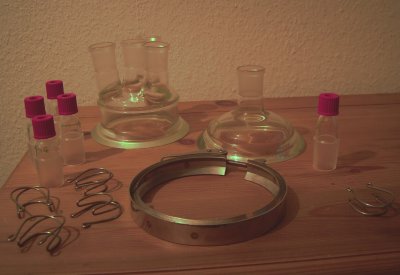
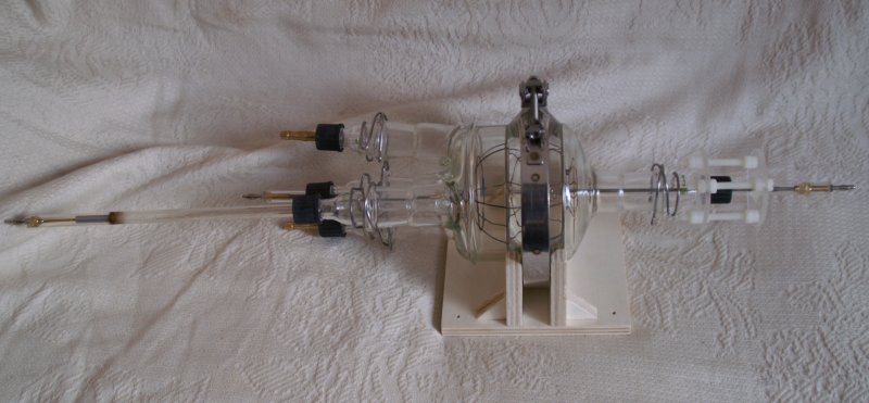
Picture 1.
The parts of the vacuum chamber are from a lab supplier. Top halves (lids) of two common plane flange joint reaction vessels with a suitable number of ground joints form the chamber's main body. The 29/32 ground joint - GL18 screwed fitting adapters are standard lab parts, too.
All Duran (pyrex) glass parts are held together by stainless steel clamps. |
To set up a vacuum chamber, the standard parts of the lab supply are quite suitable (to my opinion) - even if they're not that cheap. First, a plane flange reaction vessel is set up for both vacuum and high pressure - which means its glass is quite thick and stable. Second, the standard ground glass joints are a kind of "box of bricks" to build a wide variety of chamber geometries. Thus there is enough room for later modifications of the present setup. Last but not least ground joints are designed to be vacuum tight if the correct type of grease is applied.
Picture 2.
The assembled chamber attached to the supplies. Due to its glassy appearance I call it the "Silmaril" -- you may guess who's one of my favourite authors... ;)
For preliminary tests, only the assistant cathode was active (the long sidearm at the left side foreground) to check out the possibility of pressure measurements. The main cathode (inner grid) is not yet installed, its corresponding screwed fitting sealed by a dummy plug (red cap). |
|
 |
Electrode and pump plugs are made of 10mm Duran (pyrex) glass tube and metal sealed by epoxy - this technique proved its suitability already in building laser tubes.
The anode grid is of hard-sealed copper wires and screwed to a long thread bar inside the glass tube.
Compared to other amateur fusors the Silmaril is quite small: the chamber has a DN100 flange resulting in an anode grid diameter of only 9 cm. This is due to the fact that later pulsed tests were planned but also - money. Larger reactor vessel tops are much more expensive.
 |
|
Picture 3.
The running assistant cathode. Gas in the chamber still is air. Left side shows the extended negative glow of the discharge, to the right inside the ground joint part of the positive column which dissolves at the side of the main chamber. Also visible some E-beam fluorescence.
A current limiter 1 MegaOhm / 200W resistor is attached to the assistant cathode.
|
Unfortunately also picture 3 doesn't show that good the presence of an ion beam close to the assistant cathode. At the left end, where the discharge seems to be a little bit pinched, the cathode dark space is located. In this experiment it was 11 mm long which could be measured quite easy directly at the tube wall by help of a ruler. In air, this corresponds to a pressure of 12 Pa (0.09 Torr, 90 Micron).
I played a bit with the needle valve to check how the pressure in dynamic mode (running pump) can be regulated. Found out it's possible to get a stable throughflow down to 20 Pa (0.15 Torr) - below, it's more kind of lottery.
Negative glow at the assistant cathode has another big advantage: it automatically does kind of "spectroscopic analysis" of the chamber gas. By a small hand-held spectroscope, the characteristic lines of gas and impurities are visible. This way it can be shown in air are present: hydrogen (probably from moisture), carbon (probably from back-diffused pump oil), and a little mercury from the vacuummeter. Running in throughflow, the impurity lines become weaker - again, a limit for this seems to be around 13 Pa (0.1 Torr, 100 Micron). Below that, there's mostly dirt in the chamber.
I have to check out by longer pump runs if this betters after long time in vacuum. To be honest, I guess for practical purposes such a result will have little consequence - as with lasers, I don't like to pump for days (after setting up the stuff) until I'm clear to begin true work with the Silmaril.
Addendum: meanwhile I have a diffusion pump which makes things a lot simpler...
The Grids
After I found out my pressure measurement concept by an assistant cathode does work the next step was to set up the inner grid and its support. I chose to make it of stainless steel and quartz for these materials are relatively easy to obtain - and both of them can stand up to 1500 deg C.
As I mentioned above, there should be some kind of adjustment for the inner grid. Here I took inspration from laser mirror mounts which basically are some three-point support made of screws and springs. Due to the proximity of it to the negative voltage feed of the inner grid it must be made of some insulating material. A focussing unit which can't be touched during run is quite useless (for me).
 |
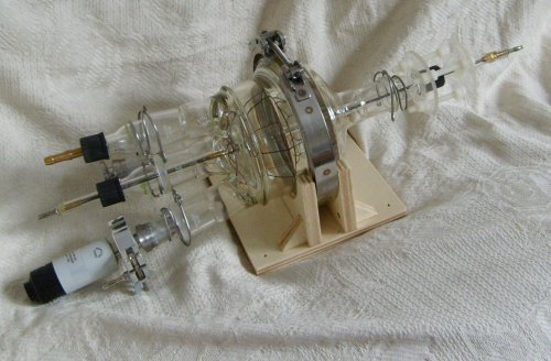
Picture 1.
The finished chamber of the Silmaril device without its supplies. Left end in a long sidearm the assistant cathode, the short center arm is the anode feed to the outer grid. Also visible the brass plugs for pump and gas supply. Right end the main cathode feed to the inner grid. By use of the three white plastic screws it may be adjusted in position relative to the outer grid's center - even while running the chamber. As mentioned, the basic idea is from a laser mirror mount. |
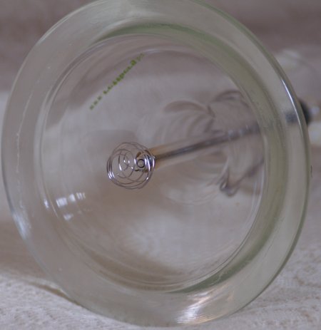
Picture 2.
View to the cathode-sided lid of the chamber with inner grid and its support.
The grid is made of a single piece of 0.8 mm stainless steel wire. A variation of the original spiral cathode concept invented by Gerardo Meiro is its double-sipral shape (which is easier to mount). Two stainless steel nuts keep it safe on a threaded stainless steel bolt surrounded by a 9 mm quartz tube. This setup shouldn't cause any problems until yellow-hot.
Total diameter of the inner grid is 20 mm. |
|
 |
 |
|
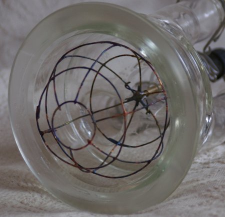
Picture 3.
The counterpart: outer grid made of hard-soldered 1.5 mm copper wire inside the anode-sided lid. This grid as well is screwed to a stainless steel bolt which in turn is surrounded by a Duran (pyrex) glass tube.
Outer grid diameter is 90 mm.
|
First complete chamber tests I again made with the assistant cathode running only. Main purpose was to find out whether the silicon rubber seal of the quartz tube (inner grid support) fails while playing around with the screws of the focusing unit. This was not the case, it kept tight. Thus it is possible to perform some movement of the inner grid while running the chamber.
Of course, with a real inner grid installed into the Silmaril, I was quite curious if it already would work as a focus diode. I replugged the assistant cathode's voltage feed (including current limiter resistor) to the main cathode. A really amazing view was the result:
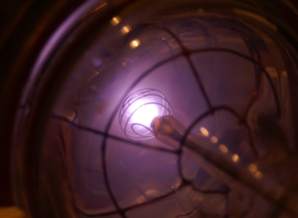
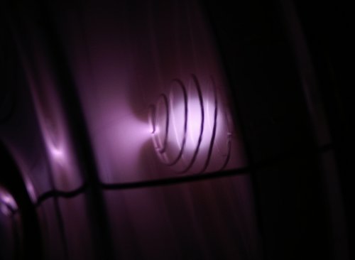
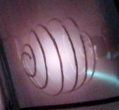
Picture 4.
View through cathode end bell to inner grid, DC operation. As with my lasers, fresh gas continuous is pumped through the chamber. At 40 Pa (0.3 Torr, 300 Micron) helium pressure a bright plasma focus (poissor) of approx. 10 mm forms inside the grid. Due to the large current limiter the grid voltage is only about 500 V. |
|
 |
 |
|
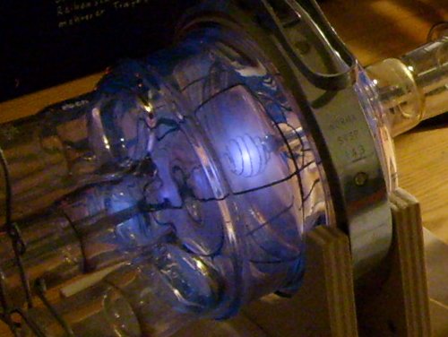
Picture 5.
Same conditions as above, view through chamber side. Slightly shorter exposure shows better the transparent appearance of the plasma focus. Also visible the chalice or bugle shaped e-beam leaving the focus.
Not visible at the photo is a weak yellow "corona" of recombining nitrogen atoms surrounding the focus, probably from air traces. Some time later I got a new spectroscope which showed an impressive band spectrum in the yellow.
|
Using a hand-held spectroscope, quite strong lines of He and He+ can be watched in the plasma focus. The latter best is noticed by observing the light green line 541 nm - both other ion lines at 486 and 656 nm are too close to hydrogen lines to decide by amateur means if it's helium ion or not. One just "guesses" 486 is stronger than in a common pure hydrogen discharge. In fact, the He ion has two close lines at 485.9 and 486.6 nm here.
Also by means of spectroscopy it is noticed below 32 Pa (0.25 Torr) impurities become more significant; the continuum becomes stronger, He lines become more diffuse until air, hydrogen and carbon dominate the spectrum and He lines are weak. It was not observed that pronounced at the assistant cathode. Another interesting fact is, the outer appearance of the plasma focus doesn't change much if the gas mixture in the chamber has more air; also, the voltage drop keeps the same. Just the colour does a minimal shift from a slightly greenish blue-white (pure He) towards a more purplish-white (high air part). The bugle jet is very slightly pink in He and white in air.
The "Pulsar" Device
Maybe nobody is surprised for the fact I set up the equipment for pulsed fusor experiments in a modular way, too.
Primary the combination of storage capacitor and spark gap (which in fact form a substantial part of the
charge transfer circuit) could be used in their own way for quite different experiments.
Of special interest is the design of the spark gap as a mechanical pulse switch. Such is used quite often in
a number of amateur metal vapor laser devives. The design in itself is simple: a metal bar rotates similar to an
aircraft propeller. Every time it is in horizontal orientation, it comes close to two metal conductors -
this results in a momentary arcing over.
The bar is driven by a long insulating glass fiber rod connected to a low voltage DC motor. The rpms (and by
this the number of pulses per second) easily can be controled via the motor voltage.
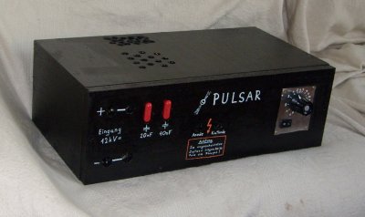 | Picture 1.
Capacitors and pulse switch in a box.
Right end the regulator knob of the motor voltage. Left is the high-
voltage compartment. A 40 nF and a 20 nF capacitor (homemade of polystyrene and aluminum sheets) can be
included - note the thick insulated red plugs. This way three different capacitor configurations are possible.
Pulse frequency can be regulated in a range of 2-16 pps.
Due to the sound it produces when running I call it the "pulsar". The sound reminds me a lot to the ticking stars
of radio astronomy. |
During testing there occured a number of problems. The schematic of the charge transfer circuit I used (see above)
is very convenient for a laser with a long thin bore but not for a short thick vessel like a fusor. Igniting the
spark gap, most of the time there is a DC discharge for the voltage drop in the main discharge is much too low to
stop it immediately.
Thus I had to change the circuit in a way no direct DC discharge via PSU and spark gap is possible. Doing so, the
power input to the tube (fusor) can be controled exactly. Part of the input energy of course is wasted in the
charging resistors, but by the Pulsar device I can put up to 52 Watts (60 nF @ 10 kV, 16 pps) independent of
pressure or other settings into the vessel.
Using the smaller capacitior configurations (20 nF, 40 nF) the dependence of pulse frequency and input power
is linear. Using 60 nF, above 10 pps power dependance drops somewhat below linearity. I guess the neon sign transformer cannot
supply the full carge current for the caps in the voltage doubler box (neon sign transformers have some kind of
built-in current limiting). A second transformer of same kind in parallel should solve the problem.
Of course I checked out what happens if I connect the Pulsar to the Silmaril device. Observation shows strong
sparks at both electrodes, similar to a poor designed nitrogen laser. Such sparks usually mean the main glow discharge
lasts too long and destabilizes into arc discharges. At lasers, there a two reasons for it: (1) too much inductance -
should be no surprise for the long HV lines connected to the Silmaril (not to forget the spiral shaped cathode grid
which basically is a coil) and (2) too much pressure. The later has to be examined seperately for the Silmaril.
Concerning inductance, one should notice for this first test the peaker capacitor was not yet installed. The formation
of the short pulses of doubled charging voltage depends mostly of it.
Addendum: some months later during a more detailed examination of the Silmaril, I found massive deposits at the glass
walls. Original of copper from the anode wires it's now copper oxide.
This should not have surprised me, for a capacitor discharge performs strong current oscillations. For a short time in each
oscillation period the outer copper grid became the cathode. Obviously this resulted in strong cathode erosion
("sputtering").
Conclusion is, the Silmaril's current electrode grids aren't suitable for pulsed discharges. So far theory...
Preparation of Low-Pressure Operation
As I announced in the theory part of this page, after the failure of the Pulsar driven discharge I decided to go low-pressure. To be honest, my vacuum equipment wasn't designed for high vacuum, not even the full power of my rotary pump could be used (as turned out).
Two points become important if pressure lowers: first, diameter of the lines has to be wide enough. That's because the mean free path of molecules becomes larger for lower pressure. On macroscopic scale the latter is recognized as increasing viscosity of the gas. To imagine the effect, think of the pump pulling honey through the lines. If a line is narrow that will become a quite hard job. So, I had to aquire a proper pump line and a proper valve.
Second, my selfmade assisstant cathode pressure gauge didn't work very well for pressures far below 0.1 Torr. Something proper was needed here, too, and I decided to spent the money for a Pirani Gauge.
A comment in advance: both was worth.
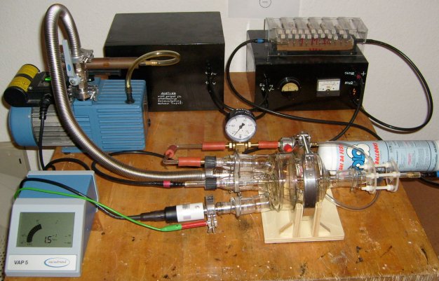
 | Picture 1.
The repaired Silmaril. I completely took it apart and removed the brownish metal oxide deposit by some mild household abrasive. Remaining water was flushed by alcohol, this helped in keeping away water vapor from the vacuum pump. The modular design made replacement of the old hose plugs by new adaptors "ground joint/ DN16 flange" quite easy. Visible at the left end is the Pirani tube which replaces the old assisstant cathode assembly.
|
Picture 2.
Modified vacuum equipment. Left side the thick silvery metal bellow hose. Directly above the pump a DN16 vacuum valve. Bottom left the controller of the Pirani gauge which displays 1.5 * 10-2 Torr in this test. Unmodified remained the helium feed line, I just removed the (now unneccessary) mercury gauge.
|
 |
Some care has to be taken if a Pirani gauge is used with helium fill. By default, the gauge has been calibrated for use with air, so the display for helium is not correct. But from tables in experimental physics books one finds a constant difference in the low pressure range values of He and air. For the reason helium has better heat conductivity than air, a constant too high pressure is displayed.
Of course I checked that, using my other vacuum gauges. Here is the result: a Pirani gauge cannot be used for pressures above 930 Pa (7 Torr; display says "normal atmospheric pressure"). In the range 133 to 800 Pa roughly the double pressure than actually inside the tube is displayed. Below 133 Pa (1 Torr), the display is constant 1.5 times the true value. So, to work with helium requires division of the display by 1.5 to get the correct pressure.
The new metal bellow hose lets the pump show its full power. Without problems I can go down to 13 Pa (0.1 Torr) for continious helium flow. Due to the fact the gas is continiously renewed, the spectroscope shows it's still quite pure at this pressure. Yet more lowering the pressure shows no air, just traces of pump oil diffusion back to the Silmaril's vessel. Clearly that's the limit of an one-staged rotary pump.
 | Picture 3.
At 13 Pa (0.1 Torr, 100 micron) helium discharge the plasma focus becomes more impressive. The colours now are as in a classical He discharge: plasma is pink, e-beam is green. The focus centers and turns smaller and more diffuse than before.
Sadly the picture doesn't display a kind of shadows which run from the wires toward the outer pink glow. Maybe that's a first hint to beginning recirculation of He ions.
|
Picture 4.
Same conditions as above, longer exposure and larger image. Contrary to operation at higher pressure the electron beam is much narrower at 13 Pa. Where it hits the glass wall blue fluorescence can be seen. The glass wall becomes quite hot in that point, it hardly can be touched.
Grid voltage raised up to 1000 volts during the experiments.
|
 |
Down to High Vacuum
After long time, writing an update of this website... already 2009 I got a diffusion pump which is perfect companion for my rotary vane pump. A general rule is - backing pump should be able to go down to 13 Pa (0.1 Torr) and should be able to suck about 2 m3 per hour. My old pump (20 years old but still top) can do so.
In December 2010 I also soldered the long-planned cascade generator. To be honest, primary need was for a CO2 laser tube which can be operated as well as a fusor with the cascade. See my laser page.
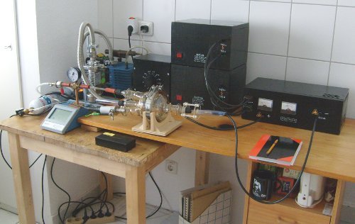 | Picture 1.
The Silmaril surrounded by the constantly growing set of lab modules. Leftmost in the back the blue rotary vane pump, in front of it the silvery diffusion pump (connected to metal bellows). In front of the pumps, a balloon helium tank and the Pirani gauge.
Behind the Silmaril's glass vessel a variac which controls both neon transformers. Which in turn feed a double cascade generator. The latter isn't fully upgraded yet, in its current state it can do 22.4kV.
Photo taken during pumping down with the diffusion pump.
|
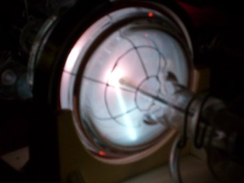
Picture 2.
My scrappy cam left me here. That's really not how it looks like, colors are different, and the rays of the starmode are hardly visible at all.
Silmaril is running here at about 2.7 Pa helium pressure (about 20 microns). Current is 5mA, grid voltage climbed up to 12kV. Visual impression is a pink star with many needle-thin rays spreading out close to the anode. Plasma focus is quite small (~1mm). Glass walls of the main chamber undergo strong blue-green fluorescence.
Due to the Silmaril's cathode coil the star looks quite different than in other amateur fusor devices. Often the latter have a cathode from few ring wires with large openings which generate 6 thicker rays. The many thin rays in the Silmaril give a stunning experience of 3D for they can be watched trough the glass walls from varying viewpoints.
|
 |
Running at low pressure and high voltage quickly gets a quite tricky exercise. Gas becomes too thin to sustain the discharge any longer, it depends more and more on the electrons emitted by the hot cathode. By practice it is possible to lower the pressure in small steps, compensate for it by simultaneous regulation of current/voltage. Doing so it is possible to keep the cathode happy hot while slowly walking down in pressure. If the discharge winks out, game is over. If the cathode cools down, even max voltage cannot start again the discharge. This way I went to 2.4 Pa / 12.5kV. Cathode already was red-hot at that point.
Currently I think about an actively heated cathode like in an old radio tube. Maybe it helps a little...
Links
Fusor.net - whatever the interested amateur wants to know about a fusor, it's a good start point to search for.
Wikipedia - about fusor and Philo Farnsworth at Wikipedia's database.
NIST - database with some spectroscopic stuff about helium and other gases.
Fusor Math - Jim Lux' website about some simple fusor calculations.
*
Acknowledgement
Special thanks to Ms. Christine Seibel for taking photos of the glow discharge and cathode ray tube and to Ms. Christiane Buck for the first Silmaril photos .
*
References
[1] Wien / Harms:
    Handbuch der Experimentalphysik (Handbook of Experimental Physics)
    Bd. XIII,3: Selbstständige Entladung in Gasen (Self-sustained Discharges in Gases)
    Akademische Verlagsgesellschaft Leipzig (1929)

[2] Wien / Harms:
    Handbuch der Experimentalphysik (Handbook of Experimental Physics)
    Bd. XIV: Kathoden- und Kanalstrahlen (Cathode and Canal Rays)
    Akademische Verlagsgesellschaft Leipzig (1929)

[3] Gmelins Handbuch der Anorganischen Chemie (Gmelins Handbook of Inorganic Chemistry)
    System-Nr.1: Edelgase (Noble Gases)
    Verlag Chemie, Weinheim (1926)

[4] Nomoto, K., Thielemann, F.-K., Miyaji, S.:
    The triple alpha reaction in accreting white dwarfs
    and neutron stars,
    Astron. Astrophys. 149(1985) p.239

[5] Adelberger, E. G. et al:
    Solar fusion cross sections
    Rev. Mod. Phys. 70(1998) p.1265

[6] Papadopoulos & Serafetinides:
    Investigation of the electrical characteristics of charge transfer circuits
    used in gas laser excitation,
    J. Appl. Phys. D 24(1991) p.1917

[7] Flügge, E. (Hrsg):
    Handbuch der Physik (Encyclopedia of Physics),
    Vol. XLIV: Nuclear Instrumentation I,
    Springer Verlag, Berlin (1959)
Created: Dec.9, 2006
© 2006-2008 Diane Neisius